Modeling of the Heat Exchange Process in the Cylinder of Diesel between the Fuel Circuit and the Air Charge- Juniper Publishers
Juniper Publishers- Journal of Oceanography
Short Communication
Studies of the process of atomization of fuel by injectors of ICE showed [1,2] that oxygen and fuel in the jet are distributed unevenly. The value of the excess air factor in the fuel flare decreases from 0.8-0.9 on its surface [3] to 0.15-0.25 at its center [4], and the droplet sizes increase from a few microns to 0. 1mm and more. The maximum diameter of the fuel droplets corresponds to the diameter of the nozzle nozzles of the injector [5].
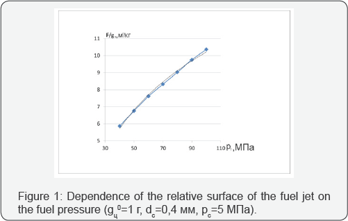
Therefore, combustion begins on the surface of the fuel jets [6], and it is the heat and mass exchange surface between the fuel injected into the engine cylinder and the surrounding air charge. Professor V.I. Odintsov [7] proposed to assign the surface of the fuel flare to the cyclic fuel supply (F/gf). With the purpose of revealing quantitative regularities of the change in the exponent F/g, a simulation was carried out when fuel was supplied through one nozzle aperture.

It has been established that with increasing fuel pressure at constant air-charge pressure and cyclic fuel supply, the surface of the fuel jet increases logarithmically Figure 1 with the confidence R2 = 0.9994 and an expression is obtained that relates the relative surface of the fuel jet to the parameters of the fuel supply process and the characteristics of the atomizer:

In expression (1), the following symbols are used: dc is the diameter of the nozzle aperture, gЦ0 is the cyclic fuel supply through one hole, PT is the fuel supply pressure, Pc is the air charge pressure. Parameters with the index «e» refer to the engine for which the quantities entering into the expression (1) are known, and the parameters with the index «p» to the engine being studied or projected [7]. Expression (1) can also be used to simulate the effect of changing the atomizer type, fuel pressure and air charge pressure on the development of the fuel flare when the technical condition of the engine changes and its fuel equipment is replaced [8]. The amount of heat transferred to the fuel cone during the processes of evaporation and mixture formation can be determined according to the Newton-Richman law:

where α is the heat transfer coefficient from the air charge to the fuel cone, BT/(M2.Н); F - the surface area of the fuel cone, M2 ΔT=TЦTOПл - the difference between the average mass temperatures of air charge and fuel, Н; τBПP - duration of injection, sec. As is known, in the absence of combustion, the fraction of heat transferred to the injected fuel with radiation does not exceed 1.5%. But with the appearance of a flame, that is, during combustion during the fuel supply period, the radiant heat flow between the flame front and the fuel drops can be significant. The radiant component of the heat flux from the flame front to the fuel droplets can be calculated using the Stefan-Boltzmann law:

where ε= 0,8...0,9 - degree of blackness of the flame, F - radiation-receiving surface of fuel droplets, C0=5,67 BT/(M2. K4) - the emission constant of an absolutely black body, Tmax -К4 the emission constant of an absolutely black body, Tmax-maximum flame temperature, TЦTOПл - temperature of fuel drops. Calculation of the heat transfer coefficient a is the subject of another article.
Conclusion
1. A dependence is presented that reflects the effect of the diameter of the nozzle openings and the differential pressure on the injection on the relative heat exchange surface between the fuel jet and the air charge.
2. The expression for modeling the influence of operating factors on the coefficient of heat transfer from the working fluid to the fuel jet will be presented in the next article.
Comments
Post a Comment