Underwater Acoustic Modem- Challenges, Technology and Applications - A Review Survey- Juniper Publishers
Juniper Publishers- Journal of Oceanography
Abstract
Today, underwater acoustic communication is developing for its various applications. For signal transmission in underwater using ocean/ sea/lakes/rivers as a medium an appropriate underwater acoustic system is required. The significant characteristic of ocean makes the underwater communication difficult using electromagnetic waves. The characteristics of an acoustic signal make a good candidate for data transfer in underwater. The underwater communication is furthermore challenging due to factors like reverberation, attenuation, scattering and sea characteristics, etc., apart from various sources of ambient noises due to natural and man made. Thus, an underwater acoustic modem plays a vital role for long distance signal transmission in underwater. Hence, it is important to study the various types of underwater acoustic modems. This paper provides a comprehensive overview of recent development and challenges in various underwater modems. This survey provides the operational classifications of modems under various frequencies. It also addresses the gaps in development of modems for long distance underwater communication.
Keywords: Underwater communication; Signal processing; High frequency modem
Introduction
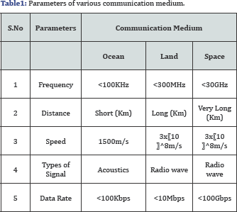
Over two third of earth's surface is covered by water. There are many areas in ocean that are unexplored. The main reason is for the minimum technological advancement in the field of oceanography compared to land and space. In recent years the underwater communication has gained massive popularity. The general classification on frequency of use, distance covered, speed of signal transmission, types of signal used, data rate etc. for various communications medium is shown in Table 1. Today, compared to terrestrial, space communication, underwater communication is one of the most difficult modes of communication. Underwater acoustic communication can be termed as the process of sending and receiving. Various signals/ messages using ocean/sea as a medium. Communication in ocean can be carried by either wired or wireless. The major issue in using the wired medium lies in the deployment cost of cables and external interventions due to aquatic animals and ships which are unavoidable. Hence, the alternative wireless medium requires more attention. Though, electromagnetic waves are used for transmission in land and space communication, it cannot be used for underwater due to the properties of ocean. Hence the alternate is an acoustic signal transmission. The velocity of sound in sea water is determined by three factors: the temperature of the water, salinity and the hydrostatic pressure. The speed of sound in underwater is high compared to terrestrial. Underwater acoustic channels have large delay spreads due to reverberation which further leads to strong frequency selectivity. Since the acoustic channel is highly variable the underwater acoustic modem is preferred for reliable underwater communication.
Classification of Acoustic Modem Based on Frequency
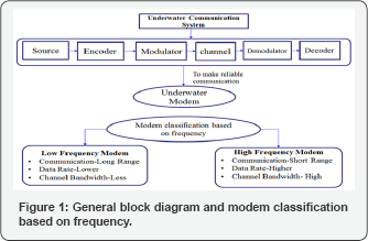
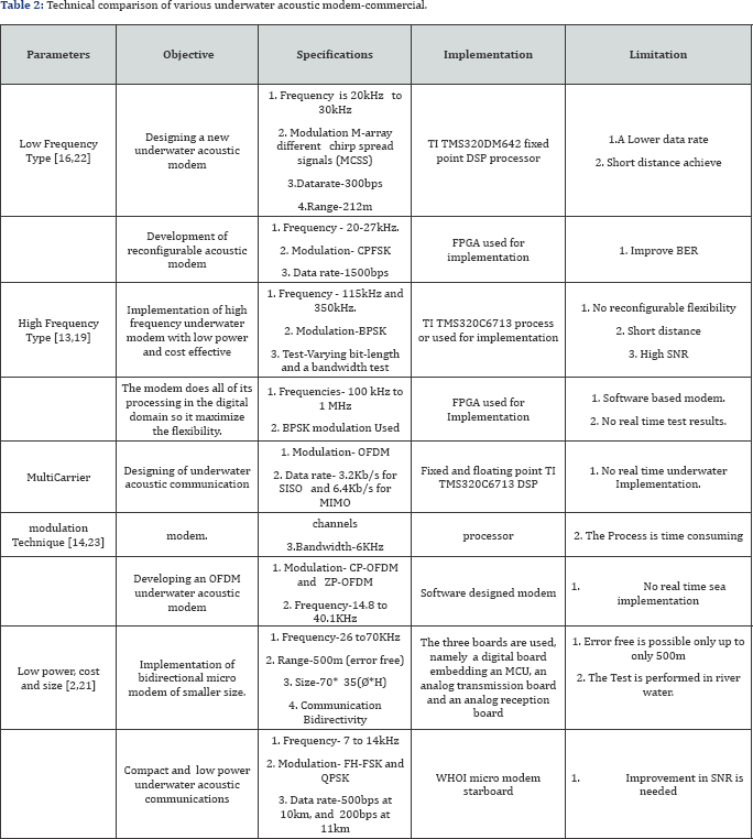
The modem is used for the purpose of effective transmission of acoustic signals in underwater. The general block diagram and modem classifications on frequencies are shown in Figure1. The underwater modems are broadly classified into two types depending on the operational frequencies as low and high frequency modems. Low frequency modems are used predominantly as they provide long range communication at low channel bandwidth which further results in low data rate. The High frequency modem provides higher bandwidth and high data rate but high frequency signal are easily absorbed in the water, which limits the usage of high frequency signals. This paper makes a comprehensive study on overview of different types of acoustic modems operating at different frequencies. Till today, many acoustic modems have been implemented for research as well as commercial purposes. Commercial modems are mostly used for data collection, underwater monitoring, positioning and telemetry.Technical parameters like modulation, bandwidth, data rate, transmission range, application and power of few underwater acoustic modems available in commercial is represented in Table 2.
Commercial modems
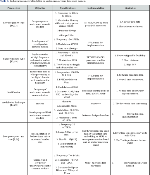
Link quest [1] sound link underwater acoustic modem uses a cutting edge broadband acoustic spread spectrum technology. The data rate achieved is 38.4kbps with a bit error rate of less than 1010 and significantly reduction in power consumption. This system features advanced hybrid modulation, channel equalization, automatic rate adaptation with suitability for horizontal and vertical environments. Aquasent[2] provides truth worthy underwater communication using OFDM, which offers high performance data transfer. To boost up the performance of the shifting sea state a special algorithm, high speed digital processor and filtering techniques were used. This has three types of model, namely AM-D2000, AM-OFDM-13A and AM-AUV. AM-D2000 used in vertical communication with a single crystal beam transducer the data rate is up to 1500bps. AM-OFDM-13A provides higher data even in multi path environment. It's used in application like oceanography and research. AM-AUV model is specially designed for autonomous underwater vehicles range is up sto 5Km depth (Table 3).
The Evo Logics [3] underwater communication modem based on sweep spread technology, which provides full duplex communication with multiple data addressing network. Each product is used in different type of application in long and short range communication. Evologics group has different modems namely S2CR 48/78, S2CR 18/34,S2CR 42/65 S2CM HS etc. Example the S2CR 18/34 modem White Line Science Edition modem enables an embedded network protocol. The modem has horizontally omnidirectional transducer beam pattern to make communication in shallow waters, the data rates up to 13.9kbps over a 3500m range with a frequency of 18-34kHz. The SNR is 10dB with smaller bit error rate less than 10-10. S2CR 18/34 on the standby mode, listen mode and receive mode consumes 2.5mW, 5- 285mW and 1.3W respectively.
Aqua Comm [4] underwater wireless modem is considered the ideal choice for underwater communications. The Aqua Comm modem is highly reliable for communications, which consumes less power with an ease of integration furthermore its small form factor and light weight. The Aqua Comm is available in 100bps and 480bps and the Aqua Comm operates with a bit rate of 10-6. Coupled with high immunity to noise and to multi-path and Doppler fading with Acoustic Doppler tolerance of±5ms-1. Broadband operation ranges between 16KHz and 30KHz. The maximum possible distance is 3km. Aqua Comm operates on Direct sequence spread spectrum/OFDM. Confirmed packet delivery with error detection. If the transmitting end does not receive an acknowledgement, it will resend the data two more times. Number of retries is configurable. Uniquely addressable, Aqua Comm provides Six digit numeric address set through host command. The voltage ranges from DC 5V to 9V.
Teledyne Benthos [5] modems are used for worldwide ocean applications. The ATM-886 provides a depth of 2000m with the weight as low as 9lbs when dry and 3lbs when wet. Its omni directional for 180° beam and directional for 60° beam.The ATM- 886 has a baud rate of 360bps and bit error rate better than 10-7 with high signal to noise ratio. It supports 704k Byte data logger standard. The processing supported are Data redundancy, 1/2 rate convolution coding multipath guard period selection MFSK and PSK modulation schemes. The distances range from 2-6km in common mode however distances can be boosted over 20km using repeaters.
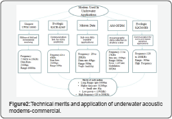
The Micron Data Modem [6] has been designed to provide a reliable communication through water. This is more suitable for AUV control system. Owing to a smaller size and light weight, its used in subsea data transfer process application. The data rate is 40bps, micron data modem provides multipath noise rejection and compact size, with low error rate, low power consumption, 500m and 150m horizontal and vertical range. Micron modem working frequency band is 20-28KHz at a data rate of 40bit S-1 with an integral range function of 0.1m resolution over full range and 0.02m accuracy. The commercial underwater acoustic modem technical merits and applications are presented in Figure 2.In future the high frequency modem development should focus on the following qualities like long range, low power, small size, and higher data rate to make an effective underwater communication.
Researcher developed modem
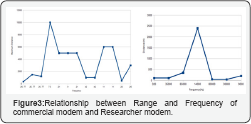
The author Benson et al. [7] developed a underwater acoustic modem proposed for short range communication with a lower data rate. Underwater transducers are typically made from piezoelectric materials and the frequency of the transducer is 35kHz with a 6kHz bandwidth. The transmitter was designed to operate for signal inputs in a range from 0 to 100kHz. The architecture has twoamplifiers; the primary amplifier is a Class AB amplifier that provides a voltage gain of 23db with the power efficiency of about 50%. The secondary amplifier is a Class D switching amplifier which is nonlinear, but possesses an efficiency of approximately 95%, both the amplifiers working together in parallel. The transmitter achieves a highly linear output. The power management system has been designed to retain transmitter efficiency maximum over the wide range of power output levels. The receiver's architecture has a set of narrow filters with high gain. These filters are based on biquad band-pass filters, and essentially combine the tasks of filtering and amplification. The current receiver configuration consumes about 375mW when in standby mode and less than 750mW when fully engaged. An ultralow-power wake up circuit will be added to the receiver to considerably reduce power consumption. Hardware platform makes use of reconfigurable hardware, particularly afield-programmable gate array, for all the digital signal processing and control required for the modem (Figure 3).
Ethem [8] developed communication modem called the reconfigurable modem, this hardware has four major parts: power supply board, the DSP board, analog-digital interface, power amplifier, and transducers. This modem implemented in TMS32OC6713 DSP, the micro-line C6713 compact board has 64Mbyte on board SDRAM as nonvolatile memory space together with local Flash File system. This FIash File system is used to store multiple modem operation in the on board memory and select the required definition at the boot time. Therefore, multiple communication algorithms are tested in a time within one deployment without the need for multiple downloads that’s provided an environment. The acoustic receiver has two major parts: the Preamble Process block and the demodulator block the samples received from the A/D converter are fist down converted to baseband. These relaxed requirements reduce the complexity of the system and speed up the simulations. The transmitter consists of an APSK modulator and a square- root raised cosine interpolation filter. A number of symbols are selected as training symbols to be used at the receiver. The transmitter employs the same filter shape for decimation. The output of the adaptive filter is converted into soft bit estimates.
Pierre et al. [9] Presented HERMES modem which is an asymmetrical underwater acoustic modem operated in two separate frequency bands. The modem operated in band between 262.5kHz and 375kHz which has sub bands like the lower sub-band (262.5kHz to 337.kHz) carries the binary information and the middle sub-band (347-373 kHz) is used for detection purposes. The acoustic uplink uses either BPSK or QPSK modulation. The uplink resides combines both parallel doppler-compensated decision feedback equalizers combined with soft-decision BCH decoding to reduce the interferences produced by the communication channel. HERMES with a phase- lock looped DFE routine which influences this complementary solution approach. This method provides smaller bit error rate with compromising the processing power. The percentage of lost messages were reduced by nearly an order of magnitude.
Tao et al. [10] developed an underwater acoustic modem based on two types of spread-spectrum techniques, namely frequency-hopping and direct sequence spread spectrum. The external synchronization method uses the low frequency modulation technique for signal synchronization. In the software design part uses the modular programming to reuse and parameter adjustment. The physical layer contains source coding, channel coding and decoding, modulation and demodulation, synchronization capture and tracking modules. Hardware uses the transducer at thefrequency band of 13- 18kHz. Currently using only four multi-point nodes underwater acoustic communication system is extended to support multiple nodes to form large covered areas of underwater acoustic communication networking systems.
The author Nusrat et al. [11] proposed a high frequency modem with large channel bandwidth with greater link capacity. The system operating frequencies from 100 kHz to 1MHz which support 1km down to under 100m. BPSK modulation and demodulation technique is used. The proposed tunable oscillator design deal with infinite frequency resolution. The modem design is implemented in FPGA with oscillator of 50MHz. The result shows that the multiplication-free filters produces same frequency and impulse response as with multiplication filter. FPGA based modem reduces the hardware cost. The reconfigurable FPGA is a suitable choice for more robust for communication system.
Hai et al. [12] proposed a modem which uses a two systems namely SISO and MIMO system with two transmitters and two receivers. MIMO OFDM has two separate data streams in parallel. This was implemented inTMS320C6713 floatingpoint DSP with the operating frequency of 225MHz. Algorithm optimization and programming optimization techniques are used for the implementation of modem, first one is algorithm optimization performed such as convolution and CFO estimation is performed and next one is programming optimization, a few new coding approaches is performed, such as loop unrolling and compiler directives, to increase the processing speed. The realtime decoding technique is performed with remarkable margins. Nonbinary LDPC coding improves the performance relative to convolutional coding.
Lingjuan et al. [13] proposed an adaptive underwater acoustic modem which changes its parameters according to the situation. Underwater acoustic modems consist of three fundamental components namely a transducer, an analog transceiver and a digital hardware platform for signal processing and control. The receiver uses a non-coherent energy detection demodulation method. In DSSS, symbols are spreading frequency domain by multiplying with a spreading code. Both simulations and sea tests are performed. The results show that the best data rate varies for different links in a network; it changes from 40 to 400b/s for FSK, and from 600 to 1900b/s for DSSS. FSK rate adaptation gives an energy saving of 63.4%. In the same way, an energy saving of 45.8% is possible for DSSS. Data were collected at two sites at distances of 265 and 638m from the transmitter. For each site, FSK and DSSS data were transmitted at six different data rates. At each data rate, 20 packets containing 2040 symbols were transmitted.
Wangwei et al. [14] presented a new underwater acoustic modem prototype design based M-ary different chirp spread signals.The transmitted and received signals used in the chirps are wave nature and acuity is proportional to bandwidth the acoustic modem. The modem is implemented in TI TMS320DM642 fixed point DSP processor with 600MHz operating frequency.The DSP encodes and decodes the chirps signal for transmission, which are contained in a packet. The former LFM is used to trigger the receiver from standby to reception mode, and the other achieves symbol synchronization. The modem is capable of transmitting between a range of 20kHz to 3kHzwith the sampling frequency of 10kHz.
Martins et al. [15] proposed a low power high data-rate acoustic modem, based on a piezoelectric poly polymer as a transducer and a Xilinx Field Programmable Gate Array (FPGA) that can be programmed to work with different types of modulations. This test was performed using an OOK 1Mbps transmission with a 1MHz single carrier, resulting in a sine period to each bit length. In the emitter side, it is possible to observe that each high logic state is converted to a 1MHz sine wave. It is noteworthy that the serial port is operating with inverted logic, meaning that a high logic state corresponds to a '0' bit and low logic state to a '1' bit. These characteristics allow for the implementation of unmanned underwater vehicles (UUV) in real time remote control with compressed video and sound or access to the internet from a submarine.
Nathan et al. [16] investigate the transmission range of an FHFSK modem operating at several different rates across three different frequency bands. Non-coherent frequency hopping, frequency shift keying allows for a robust, low- cost physical layer solution that is particularly suited for low rate communications.Frequency hopping divides the useable bandwidth into orthogonal frequency bins. Frequency hopping can be exploited in a multi-user environment in order to share the available bandwidth by allowing a number of users to transmit simultaneously on different hopping patterns. Performance of FH-FSK at four different data rates across three different frequency bands: 7.44-12.24 KHz, 12.56-17.36 KHz, and 22.8-27.6KHz similar to those in the Micro-modem. These three frequency bands will be denoted as the 9 kHz band, the 14 kHz band, and the 2kHz band. The absorption coefficient of the acoustic medium plays a critical role in determining the received signal power, and thus, the probability of error at the receiver. This will greatly influence the deployment of an underwater network. Nodes that use the 25kHz bandwidth will need to be spaced densely within an area in order to ensure communication. However, in the 9kHz band, nodes that are separated by greater distances will have a greater chance of collisions by due to overlap of simultaneous transmissions since the received signal power decays much less slowly with distance.Brady et al. [17] proposed a design to build a platform for underwater acoustic communication research with high frequency, large bandwidth, and low power design. The frequencies used in this system were 115kHz and 351kHz. The system has to channel the transmit channel and the receive channel. The transmit channel is comprised of the DSP, the power amplifier, the tuning indicator and the broadband transducer. The receive channel is made up of the transducer as a source, protection circuitry, a fully differential pre-amplifier, an analog-to-digital converter and the DSP. This modem is implemented in TMS320C6713 with resonance around 110kHz, and the other at 304kHz. There were two functional tests which were at varying bit-length test, and a bandwidth test. The setup for the bit-length test for the 115kHz transducer, for this test, the bandwidth was constant at 57.6kHz. The length of the M-sequence was increase from 255 bits to 2047 bits. The setup for the bandwidth test for the 115kHz transducer, as the bandwidth increases from 11.5kHz to 57.6kHz one can note that the path resolution is increased.
Future direction for underwater modem
These comparative studies on various acoustic modems explain that the performance of the systems depends on the following likes type of modulation, implementation board, frequency and transducer and power consumed. The commercial modem can achieve long distance with higher energy consumption. The following will explain about the improvement study on the underwater modem to enhance the performance of the system in terms of power, bandwidth and simulation model.
Antonio [18] presents modem design with Asynchronous wakeup circuit in order to avoid the additional transducer in the modem with lower energy consumption. An acoustic wake up circuit is used to minimize the power consumption in the transmitter and receiver. The system remains in idle state until it receives wakeup signals also the sleep mode saves when the system in idle state. Push-pull amplifier is directely connected to the wilkinson power divided circuit to minimize the power consumption. A case study has been done in ITACA modem prototype. In this type of prototype Power consumption is not increased in wake up or in sleep mode when the additional circuit is added to the network.
Albert [19] proposed an asynchronous idle power management system along with the properties of acoustic modem. Two techniques is used for idle-time power management to improve the energy efficiency in underwater acoustic modem is compared. The evaluation is performed based on the four types of protocols namely Standard idle mode, optimum sleep, STEM mode and Wakeup mode is performed in terms of energy consumption, to minimize the power with lowest cost. This shows that wakeup mode saves energy than sleep cycling mode.
Alexander [20] proposed an algorithm for AUVs. An algorithm provides possible solution to the acoustic modem where the range and estimation of dead line measurement. This algorithm is best suitable in the bandwidth limited environment. The algorithm will compute a range-measurement outlier by using the past range measurements. When the bandwidth is limited a new position estimation is performed to solve the problem although this is inexpensive and its continuously will run in main vehicles computer of underwater applications. The information collected from the one vehicle is periodically shares the information to others, so there is no extra bandwidth is needed to transmit information.
The underwater communication behaviors are unpredictable by the human begins. It's difficult to forecast the signal what happens in transmitter and receiver side. For this purpose a simulator and modelling tools are developed to test the signals. P Xie [21] proposed a network simulator called Aqua-Sim, for simulating underwater sensor networks. Aqua-Sim can simulate the collision behaviors in long delay acoustic networks and the signal attenuation that underwater acoustic channels can suffer. In addition, this simulator is able to simulate three-dimensional network deployment and authors added several protocol definitions to make it more accurate. Aqua-Sim higher energy consumption and packet deliver ratio than others [22-26].
Existing mechanisms for conventional modems need to be modified, or even interchanged to suit the newly emerged technology. The view and progress expected for development of high frequency underwater modems as shown in Figure 4 should address on the following issues [26-31]
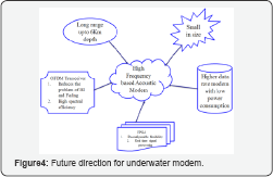
- Longer distance transmission (more than 6kms),
- Smaller size (at least 50% less in size compared to modems that are used for terrestrial and space communication),
- High Data rate (More than 10kbps)
- Low power consumption
- Various modulation techniques (OFDM the excessive compact of attenuation due to its promises for higher data rate)
- Implementation for real time applications (FPGA- Provides greater reconfigurable flexibility).
The recommended plan for the future development of underwater acoustic communication modem is presented below. High frequency acoustic modem has to be designed with low power consumption and software reconfigurable. By incorporating suitable modulation, equalization and coding techniques, the communication has to be highly immune to noise and multi-path fading. Modem controls of analog card and digital card and power supply modules are to be assembled in a rugged mechanical valise. The digital card has to be designed around a suitable DSP processor and a low power FPGA. The analog card has to provide signal conditioning and amplification for transmission and reception acoustic signals through underwater acoustic transducer. Power supply I/P, Transducer interface and RS 232 interface can provide on the mechanical valise. The design and development of underwater acoustic modem meant for underwater communication system between the on-shore control station and underwater device. The communication is two way and is in full duplex mode. To make an effective communication in underwater the designed acoustic modem should have the following specification [32].
General Specification
Modem has to be designed and developed with low power consumption and software reconfigurable. The modem consists of two cards:
- Analog card and
- Digital card.
The specifications of each card are given below.
A. Implementation of modulation techniques:
a. OFDM modulation
b. QPSK modulation
c. Chip slope keying
B. Implementation of coding techniques:
Convolution encoder with interleaver at transmitter chain and Viterbi decoder with interlever in receiver chain.
1. Development of Algorithms for channel estimation.
2. The carrier frequency for QPSK modulation is 48khz and for CSK modulation 24 to 48Kh .
3. Band rate is selectable from 100 to 4000 bits/s.
4. Bit error rate should be less than 10-6
5. The communication operating depth is upto 4000m.
6. Source level should be from 185 dBupa@1m.
7. SNR: 30dB.
8. Electrical power of o/p of power amplifier should be up to 60W.
9. The Pre-amplifier gain should be adjustable up to 100dB.
10. Modem should have Rs.232 serial interface.
11. The electrical parameters of modem are given below.
a. Input operating Voltage: 28VDC, other required voltages are to be generated using DC-DC converter or voltage regulators.
b. Current in power down mode: To be minimum.
c. Max current in transmitting mode: 4A
d. Transmitter power: 60W
12. Each mode consists of Analog card digital card and power supply modules are to be assembled in a rugged mechanical valise. Analog and digital card specifications are given below with the diagrams.
Digital card specification
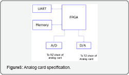
The general block diagram of digital card is shown in Figure 5 which includes the followings like UART, Memory, FPGA, Analog to Digital converter and Digital to Analog Converter.
1. The digital card has to be designed around a suitable DSP processor and a low power FPGA by
2. Xilinx makes.
3. Memory:
a. Flash: 16MB,
b. RAM: 128MB,
c. NAND Flash: 4GB
4. A/D converter:
a) Type: 18 bit, SAR converter,
b) Sampling frequency: 200KHz. And
c) AD 7608 or equipment.
5. D/A converter:
a. 16 bit DAC and
b. Settling time 4μs.
Analog Card Specification
The general block diagram of Analog card is given below in Figure 6 which has the following elements, namely pre amplifiers, Automatic gain controller, Band pass filter, Drive amplifier, Reconstruction filters etc.
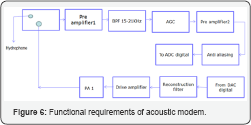
Pre-Amplierl:
- Gain: 10dB,
- Input voltage range: 1|xv -10|iv,
- Impedance matching: should be coupled with capacitive transducer and
- Make: AD 624SD or equivalent.
Automatic gain control specifications
a. Operating frequency: 16-20KHz,
b. Make: AD 8332 or Equivalent.
5.3. Pre-amplifier 2:
a. Gain: Adjustable up to 100dB and
b. Operating frequency: 16-20KHz.
Band pass filter
Operating frequency
- 15-21kHz,
- Pass band gain: 10dB
Stop Band Attenuation:
a) 40dB
b) Type: Chebyshev and
c) Order: 8
Anti-aliasing filter
Low pass filter with cutoff frequency 100khz
5.8. Programmable driver amplifier
Gain adjustments from FPGA.
Power amplifier
- Type: Bridge mode power amplifier,
- Operating frequency: 16-20 kHz
Output power:
- Variable power output up to 60W,
- Impendence matching: should be coupled to capacitive transducer and
- Make: Power booster PB 58A. Wake up circuit is added to reduce power consumption.
Functional Requirements of Acoustic Modem
- The data transmission should be in packets/frames with proper protocol and acknowledgment.
- The protocol should be an error control protocol with error detection and correction technique to establish reliable communication between ship and underwater device (UWD). The modem will be placed in ship.
- Communication will be in half duplex mode. By incorporating suitable digital signal processing techniques, the communication has to be highly immune to noise and multi-path fading.
- The entire system should be compact with low operating power requirement.
Development of software and firmware
Acoustic modem has to be interfaced to PC through USB post for user interaction. The following software modules are to be developed as part of the Modem. Test software (monitor) running in target processor to test all the hardware resources of the modem.
- A front-end GUI based software running on PC for user interaction and to send commands to modem.
- A modem application program running in target for two way communication. In the modem application program, there should be provision to select modulation scheme, coding type, band rate, power level, etc. the data file has to be uploaded from PC to modem for transmission. Similarly the software should be able to download the data received from the modem into PC for display. The modem application may be split between processor and FPGA as convenient.
Conclusion
Most of the underwater modems operate in low frequency. While using high frequency, low attenuation, high bandwidth and higher data rate can be achieved, but by compromising the range to a few thousand meters. An overview of commercial and under research underwater acoustic modem is presented in this paper. Several factors that do not exist in low power modem impose fundamental limitations on their performance. The technical challenges existing and can be eliminated in future is also addressed. This paper specifies some key configuration parameters that needs to be concentrated on to improve the performance of the high frequency modem.
To Know More About Journal of Oceanography Please Click on: https://juniperpublishers.com/ofoaj/index.php
To Know More About Open Access Journals Publishers Please Click on: Juniper Publishers
Comments
Post a Comment